- Rack-mounted Lithium Battery
- Golf Cart Lithium Battery
-
Golf Cart Lithium Battery
- 36V 50Ah (for Golf Carts)
- 36V 80Ah (for Golf Carts)
- 36V 100Ah (for Golf Carts)
- 48V 50Ah (for Golf Carts)
- 48V 100Ah (Discharge 100A for Golf Carts)
- 48V 100Ah (Discharge 150A for Golf Carts)
- 48V 100Ah (Discharge 200A for Golf Carts)
- 48V 120Ah (for Golf Carts)
- 48V 150Ah (for Golf Carts)
- 48V 160Ah (Discharge 100A for Golf Carts)
- 48V 160Ah (Discharge 160A for Golf Carts)
-
Golf Cart Lithium Battery
- Forklift Lithium Battery
- 12V Lithium Battery
- 24V Lithium Battery
- 36V Lithium Battery
- 48V Lithium Battery
-
48V LiFePO4 Battery
- 48V 50Ah
- 48V 50Ah (for Golf Carts)
- 48V 60Ah (8D)
- 48V 100Ah (8D)
- 48V 100Ah
- 48V 100Ah (Discharge 100A for Golf Carts)
- 48V 100Ah (Discharge 150A for Golf Carts)
- 48V 100Ah (Discharge 200A for Golf Carts)
- 48V 150Ah (for Golf Carts)
- 48V 160Ah (Discharge 100A for Golf Carts)
- 48V 160Ah (Discharge 160A for Golf Carts)
-
48V LiFePO4 Battery
- 60V Lithium Battery
-
60V LiFePO4 Battery
- 60V 20Ah
- 60V 30Ah
- 60V 50Ah
- 60V 50Ah (Small Size / Side Terminal)
- 60V 100Ah (for Electric Motocycle, Electric Scooter, LSV, AGV)
- 60V 100Ah (for Forklift, AGV, Electric Scooter, Sweeper)
- 60V 150Ah (E-Motocycle / E-Scooter / E-Tricycle / Tour LSV)
- 60V 200Ah (for Forklift, AGV, Electric Scooter, Sweeper)
-
60V LiFePO4 Battery
- 72V~96V Lithium Battery
- E-Bike Battery
- All-in-One Home-ESS
- Wall-mount Battery ESS
-
Home-ESS Lithium Battery PowerWall
- 24V 100Ah 2.4kWh PW24100-S PowerWall
- 48V 50Ah 2.4kWh PW4850-S PowerWall
- 48V 50Ah 2.56kWh PW5150-S PowerWall
- 48V 100Ah 5.12kWh PW51100-F PowerWall (IP65)
- 48V 100Ah 5.12kWh PW51100-S PowerWall
- 48V 100Ah 5.12kWh PW51100-H PowerWall
- 48V 200Ah 10kWh PW51200-H PowerWall
- 48V 300Ah 15kWh PW51300-H PowerWall
PowerWall 51.2V 100Ah LiFePO4 Lithium Battery
Highly popular in Asia and Eastern Europe.
CE Certification | Home-ESS -
Home-ESS Lithium Battery PowerWall
- Portable Power Stations
Understanding Voltage in Series and Parallel Circuits

In the realm of electrical engineering, the behavior of voltage in circuits is a fundamental concept that dictates how electrical components interact within a system. Whether we are dealing with series circuits or parallel circuits, understanding how voltage behaves in each configuration is crucial for designing and troubleshooting electronic systems. In this comprehensive guide, we will delve into the specifics of voltage distribution in both series and parallel circuits, shedding light on the principles that govern their operation.
Voltage in Series Circuits
Series circuits are characterized by components connected end-to-end, forming a single path for current to flow. This configuration has distinct implications for voltage distribution.
Total Voltage in Series Circuits
In a series circuit, the total voltage supplied by the power source is distributed across each component in the circuit. This distribution is not uniform but rather proportional to the resistance of each component. According to Ohm’s Law, the voltage drop across a component in a series circuit is given by:
Vi=I×RiV_{i} = I \times R_{i}
where ViV_{i} is the voltage drop across the ii-th component, II is the current through the circuit (which is the same for all components in a series circuit), and RiR_{i} is the resistance of the ii-th component.
Voltage Drops Across Components
The voltage drop across each component in a series circuit varies based on its resistance. The sum of these voltage drops equals the total voltage supplied by the source. Mathematically, this can be expressed as:
Vtotal=V1+V2+…+VnV_{total} = V_{1} + V_{2} +
where VtotalV_{total} is the total voltage supplied, and V1,V2,…,Vn. are the individual voltage drops across each component.
Practical Implications
In practical applications, this means that if one component in a series circuit fails or is removed, the entire circuit is interrupted. This is because the current has only one path to flow, and any break in this path will stop the current from circulating.
Voltage in Parallel Circuits
Parallel circuits, on the other hand, offer a different way of connecting components. Each component is connected across the same two points, creating multiple paths for current to flow.
Uniform Voltage Across Components
In a parallel circuit, the voltage across each component is the same. This occurs because each component is connected directly across the power source’s terminals, resulting in identical potential differences across each component. The voltage across any component in a parallel circuit is given by:
Vi=VtotalV_{i} = V_{total}
where ViV_{i} is the voltage across the ii-th component, and VtotalV_{total} is the total voltage of the power source.
Current Distribution
While the voltage remains constant across each component, the current through each branch of the parallel circuit varies depending on the resistance of each component. The total current supplied by the power source is the sum of the currents through each parallel branch:
Itotal=I1+I2+…+InI_{total} = I_{1} + I_{2} +
where ItotalI_{total} is the total current from the source, and I1,I2,…,InI_{1}, I_{2}, \ are the currents through each branch.
Reliability and Flexibility
Parallel circuits are often used in applications where reliability and flexibility are important. If one component fails or is removed, the remaining components continue to function because the current can flow through the other paths. This makes parallel circuits suitable for applications such as household wiring, where multiple devices can operate independently.
Comparative Analysis: Series vs. Parallel Circuits
Understanding the differences between series and parallel circuits helps in selecting the appropriate configuration based on the requirements of an application. Here’s a comparative analysis:
Voltage Behavior
- Series Circuits: The total voltage is divided among components; each component experiences a different voltage drop.
- Parallel Circuits: The voltage across each component is the same as the total voltage.
Current Behavior
- Series Circuits: The same current flows through all components, and the total current is the sum of the individual currents through each component.
- Parallel Circuits: The current splits among the branches, and the total current is the sum of the currents through each parallel branch.
Impact of Component Failure
- Series Circuits: A failure in one component affects the entire circuit.
- Parallel Circuits: A failure in one component does not affect the operation of the other components.
Applications and Examples
Series Circuit Applications
- Christmas Lights: Traditional Christmas lights are often wired in series. If one bulb fails, the entire string of lights goes out.
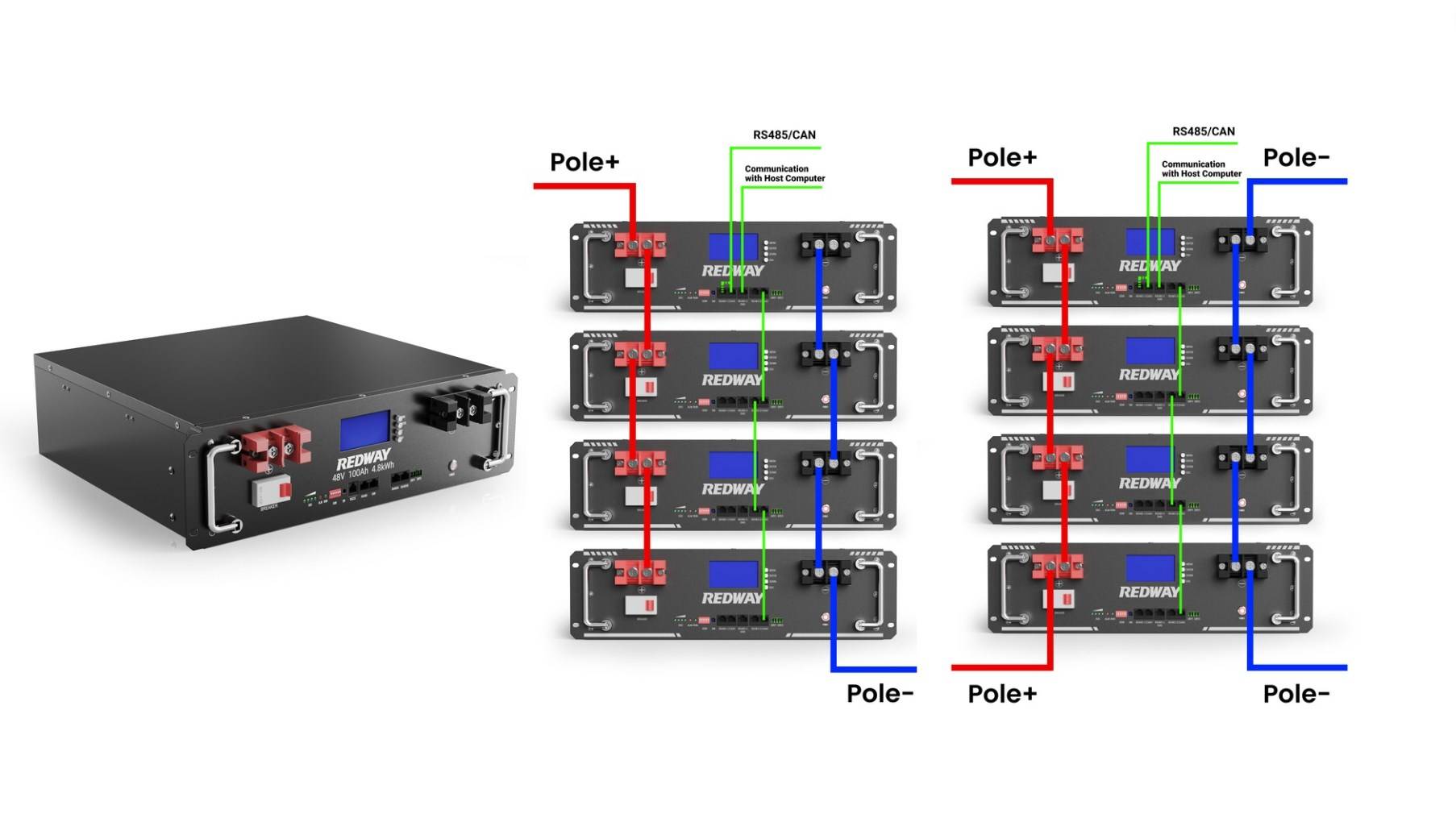
- Battery Chains: Batteries connected in series increase the total voltage available, such as in a flashlight.
Parallel Circuit Applications
- Home Electrical Systems: Household wiring typically uses parallel circuits to ensure that each appliance receives the same voltage and continues to function if another appliance fails.
- Computer Components: Internal components like hard drives and memory modules are connected in parallel to ensure they operate independently.
Conclusion
In summary, the behavior of voltage in series and parallel circuits is governed by fundamental principles that dictate how electrical energy is distributed and utilized. In series circuits, voltage is divided among components, leading to varying voltage drops, while in parallel circuits, each component experiences the same voltage. Understanding these differences is crucial for designing efficient and reliable electrical systems. By recognizing the unique characteristics and applications of both circuit types, we can make informed decisions in both theoretical and practical electrical engineering contexts.


