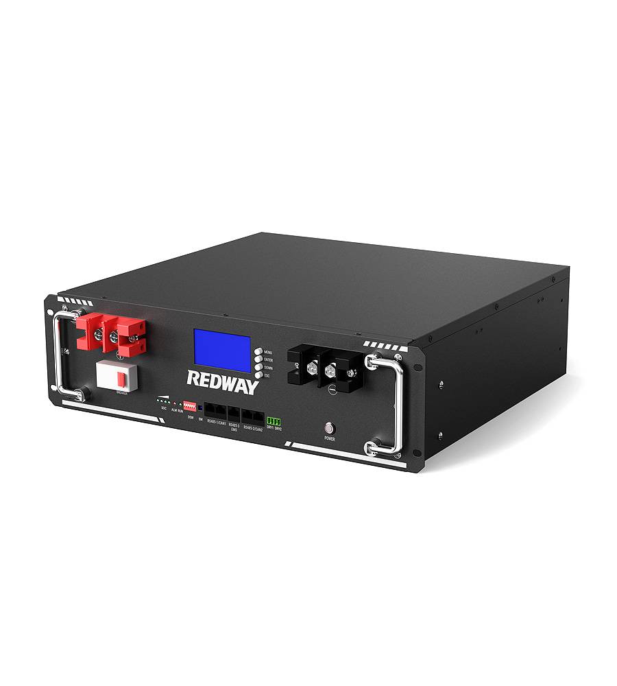
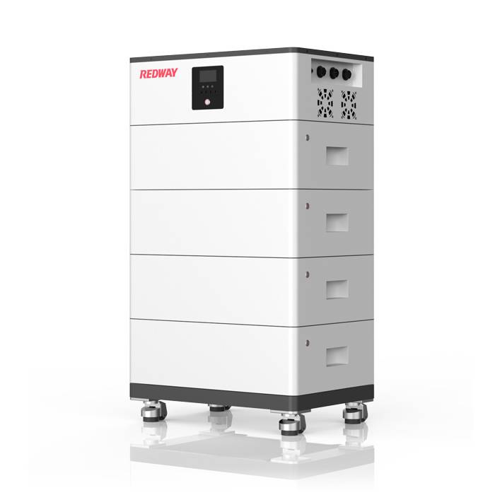
- Rack-mounted Lithium Battery
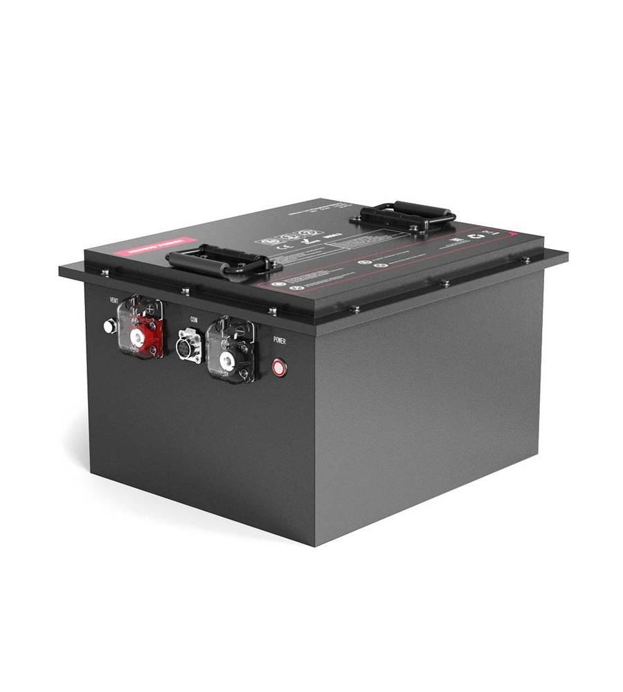
- Golf Cart Lithium Battery
-
Golf Cart Lithium Battery
- 36V 50Ah (for Golf Carts)
- 36V 80Ah (for Golf Carts)
- 36V 100Ah (for Golf Carts)
- 48V 50Ah (for Golf Carts)
- 48V 100Ah (Discharge 100A for Golf Carts)
- 48V 100Ah (Discharge 150A for Golf Carts)
- 48V 100Ah (Discharge 200A for Golf Carts)
- 48V 120Ah (for Golf Carts)
- 48V 150Ah (for Golf Carts)
- 48V 160Ah (Discharge 100A for Golf Carts)
- 48V 160Ah (Discharge 160A for Golf Carts)
-
Golf Cart Lithium Battery
- Forklift Lithium Battery
- 12V Lithium Battery
- 24V Lithium Battery
- 36V Lithium Battery
- 48V Lithium Battery
-
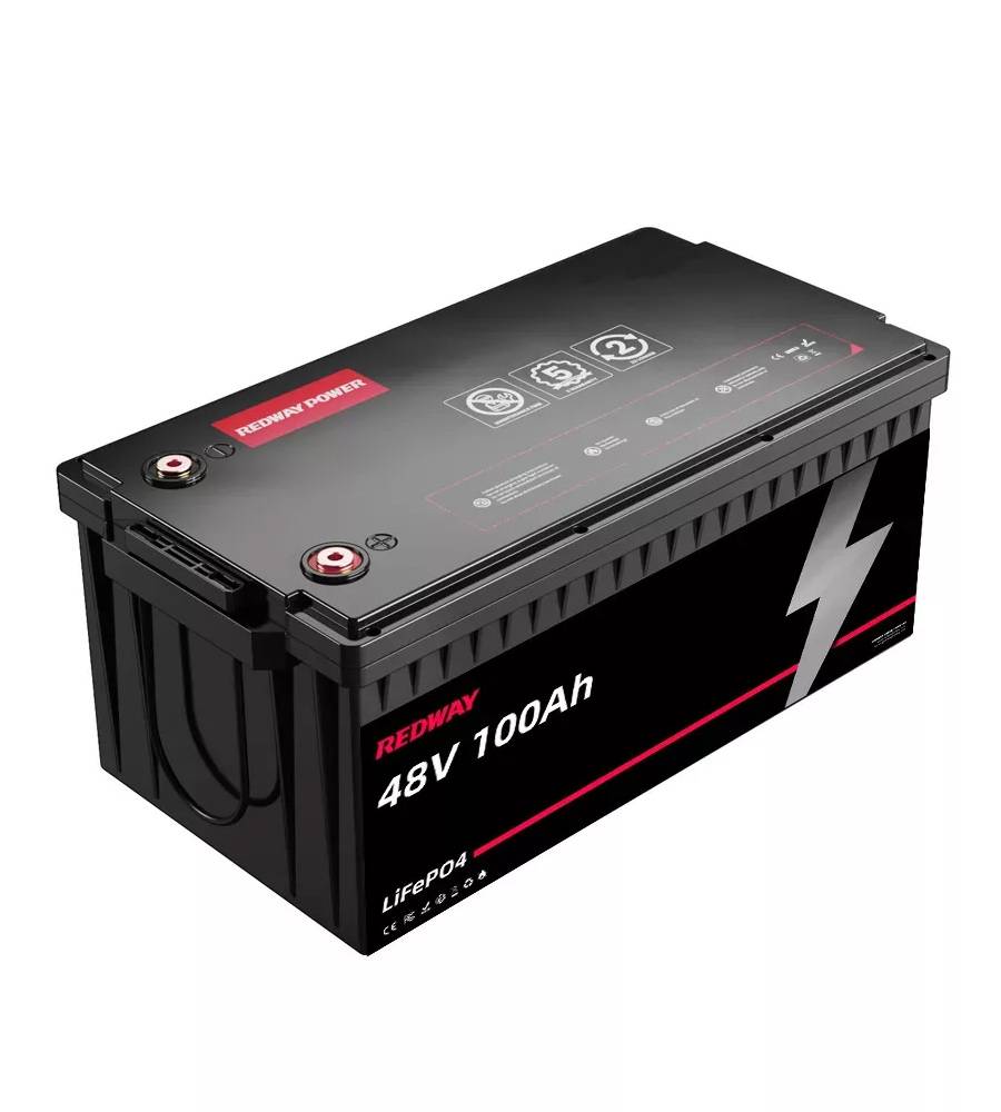
48V LiFePO4 Battery
- 48V 50Ah
- 48V 50Ah (for Golf Carts)
- 48V 60Ah (8D)
- 48V 100Ah (8D)
- 48V 100Ah
- 48V 100Ah (Discharge 100A for Golf Carts)
- 48V 100Ah (Discharge 150A for Golf Carts)
- 48V 100Ah (Discharge 200A for Golf Carts)
- 48V 150Ah (for Golf Carts)
- 48V 160Ah (Discharge 100A for Golf Carts)
- 48V 160Ah (Discharge 160A for Golf Carts)
-
48V LiFePO4 Battery
- 60V Lithium Battery
-
60V LiFePO4 Battery
- 60V 20Ah
- 60V 30Ah
- 60V 50Ah
- 60V 50Ah (Small Size / Side Terminal)
- 60V 100Ah (for Electric Motocycle, Electric Scooter, LSV, AGV)
- 60V 100Ah (for Forklift, AGV, Electric Scooter, Sweeper)
- 60V 150Ah (E-Motocycle / E-Scooter / E-Tricycle / Tour LSV)
- 60V 200Ah (for Forklift, AGV, Electric Scooter, Sweeper)
-
60V LiFePO4 Battery
- 72V~96V Lithium Battery
- E-Bike Battery
- All-in-One Home-ESS
- Wall-mount Battery ESS
-
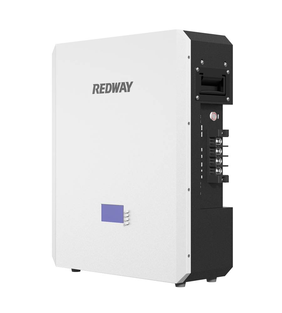
Home-ESS Lithium Battery PowerWall
- 24V 100Ah 2.4kWh PW24100-S PowerWall
- 48V 50Ah 2.4kWh PW4850-S PowerWall
- 48V 50Ah 2.56kWh PW5150-S PowerWall
- 48V 100Ah 5.12kWh PW51100-F PowerWall (IP65)
- 48V 100Ah 5.12kWh PW51100-S PowerWall
- 48V 100Ah 5.12kWh PW51100-H PowerWall
- 48V 200Ah 10kWh PW51200-H PowerWall
- 48V 300Ah 15kWh PW51300-H PowerWall
PowerWall 51.2V 100Ah LiFePO4 Lithium Battery
Highly popular in Asia and Eastern Europe.
CE Certification | Home-ESS -
Home-ESS Lithium Battery PowerWall
- Portable Power Stations
What is the Difference Between Series and Parallel Circuits?
Understanding the fundamental differences between series and parallel circuits is crucial for anyone delving into electronics. These two types of circuits define how components are arranged and interact within an electrical system. Each configuration offers distinct advantages and has unique characteristics that determine their suitability for various applications.
Series Circuits: A Single Pathway
In a series circuit, components are connected end-to-end, forming a single continuous path for current flow. This arrangement means that the same current flows through each component sequentially.
Current Flow in Series Circuits
In a series circuit, the current remains constant throughout all components. This characteristic is fundamental to understanding series circuits. Regardless of the number of components, the current does not change as it passes through each one.
Voltage Distribution in Series Circuits
The voltage across each component in a series circuit can vary. The total voltage of the circuit is the sum of the voltages across each component. For instance, if a circuit comprises three resistors, the total voltage of the power source is divided among them. This division is based on the resistance of each component.
Impact of Component Failure
A significant drawback of series circuits is their susceptibility to failure. If one component fails, the entire circuit is interrupted. This characteristic makes series circuits less reliable for applications where continuity is critical.
Practical Applications of Series Circuits
Series circuits are often used in applications where a consistent current is needed through multiple components. Examples include:
- Christmas lights: Traditional Christmas lights often use series circuits. If one bulb fails, it can cause the entire string of lights to go out.
- Voltage dividers: These circuits are used to produce a voltage that is a fraction of the input voltage. This is useful in various electronic devices for controlling voltages.
Parallel Circuits: Multiple Pathways
In contrast, parallel circuits connect components alongside each other, forming multiple paths for current to flow. This configuration ensures that each component has the same voltage across it.
Voltage in Parallel Circuits
In parallel circuits, the voltage across each component is identical to the total voltage of the power source. This uniform voltage distribution is a defining characteristic of parallel circuits.
Current Distribution in Parallel Circuits
The current in a parallel circuit can vary for each component. The total current is the sum of the currents through each parallel branch. This allows different components to draw different amounts of current based on their individual resistance.
Component Failure in Parallel Circuits
A key advantage of parallel circuits is their resilience to failure. If one component fails, the other components continue to function unaffected. This characteristic makes parallel circuits ideal for applications requiring reliability.
Practical Applications of Parallel Circuits
Parallel circuits are widely used in scenarios where it is crucial to maintain the functionality of the entire system despite the failure of individual components. Examples include:
- Household wiring: Most home electrical systems use parallel circuits. This allows multiple appliances to operate independently of each other.
- Automotive lighting: Car headlights and other lighting systems use parallel circuits to ensure that if one light fails, others remain operational.
Comparing Series and Parallel Circuits
To summarize, both series and parallel circuits have unique attributes that make them suitable for different applications. Understanding these differences is essential for designing and troubleshooting electrical systems.
Key Differences
- Current Flow:
- Series: Same current flows through all components.
- Parallel: Current can vary in each branch.
- Voltage:
- Series: Voltage is divided among components.
- Parallel: Voltage is the same across all components.
- Failure Impact:
- Series: Entire circuit fails if one component fails.
- Parallel: Other components continue to operate if one fails.
Choosing the Right Circuit
The choice between series and parallel circuits depends on the specific requirements of the application. Series circuits are useful when the same current is needed through all components, whereas parallel circuits are preferable for applications needing consistent voltage across components and high reliability.
Advanced Considerations
For more complex applications, combinations of series and parallel circuits are often used. These series-parallel circuits leverage the benefits of both configurations, enhancing performance and reliability.
Series-Parallel Circuits
In a series-parallel circuit, groups of components are connected in series with other groups in parallel. This hybrid approach is common in battery configurations, where several cells are connected in series to increase voltage, and these series groups are then connected in parallel to increase capacity.
Analyzing Complex Circuits
Understanding the principles of series and parallel circuits is foundational for analyzing and designing more complex electrical systems. Tools like Ohm’s Law and Kirchhoff’s Circuit Laws are essential for calculating current, voltage, and resistance in these hybrid circuits.
Conclusion
In conclusion, grasping the differences between series and parallel circuits is vital for anyone working with electrical systems. Series circuits provide a single path for current with voltage divided among components, while parallel circuits offer multiple paths with consistent voltage across each component. Each type has its unique advantages and is chosen based on the specific needs of the application. By leveraging the strengths of both configurations, we can design robust and efficient electrical systems suitable for a wide range of applications.
